Printhead Card Manager + SoM board
Component Fitting Instructions
These instructions detail how to fit any of the supplied components listed below to the Printhead Card Manager E assembly (supplied as two boards assembled – Printhead Card Manager and CPU).
Tools Required
Safety Warning

2.5mm Hex driver or hexagon Allen Key

ESD Wrist Strap and cord

Use a torque screwdriver or wrench to tighten the PCB mounting screws or nuts to 0.5N.m/5.1kg.cm.

Over-tightening mounting screws or nuts permanently deforms the fibre-glass material of PCBs. This PCB damage can make the circuit malfunction.
1200332
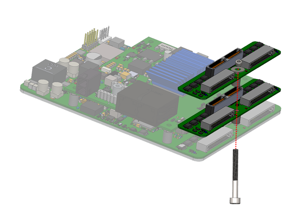
Signal Relay E for Multiple Printhead Manager Boards
- Gently place the Signal Relay-Multiple board into the desired position, be careful to insert the pins correctly.
- Fit the supplied M3 bolt and washer.
- Tighten the bolt to secure the Signal Relay-Multiple in place.
(Click image to magnify)
(Click image to magnify)
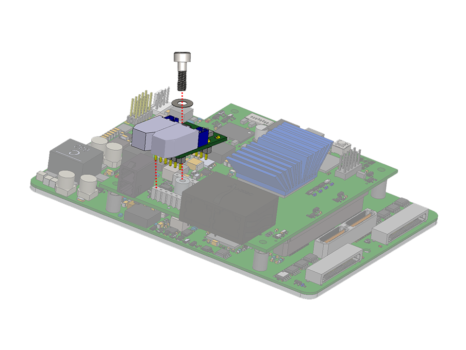
1200431 / 1200432
Signal Manager (Product Detect 5/12V/24V)
- Remove and discard the two M3 bolts that are securing the CPU board to the main board.
- Place and hold a spacer beneath the Signal Manager (Either 5/12V or 24V) board and gently fit the board into the desired position, be careful to insert the pins correctly.
- Fit the supplied M3 bolts, washers and nuts.
- Tighten the nuts to secure the Signal Manager in place.
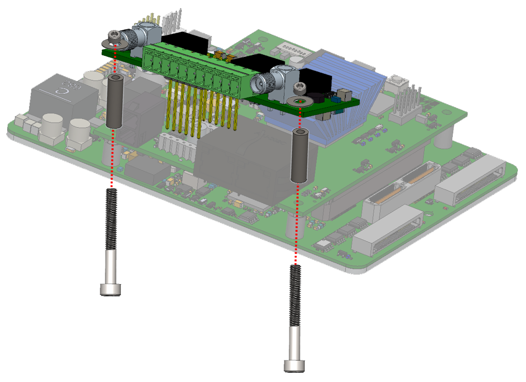
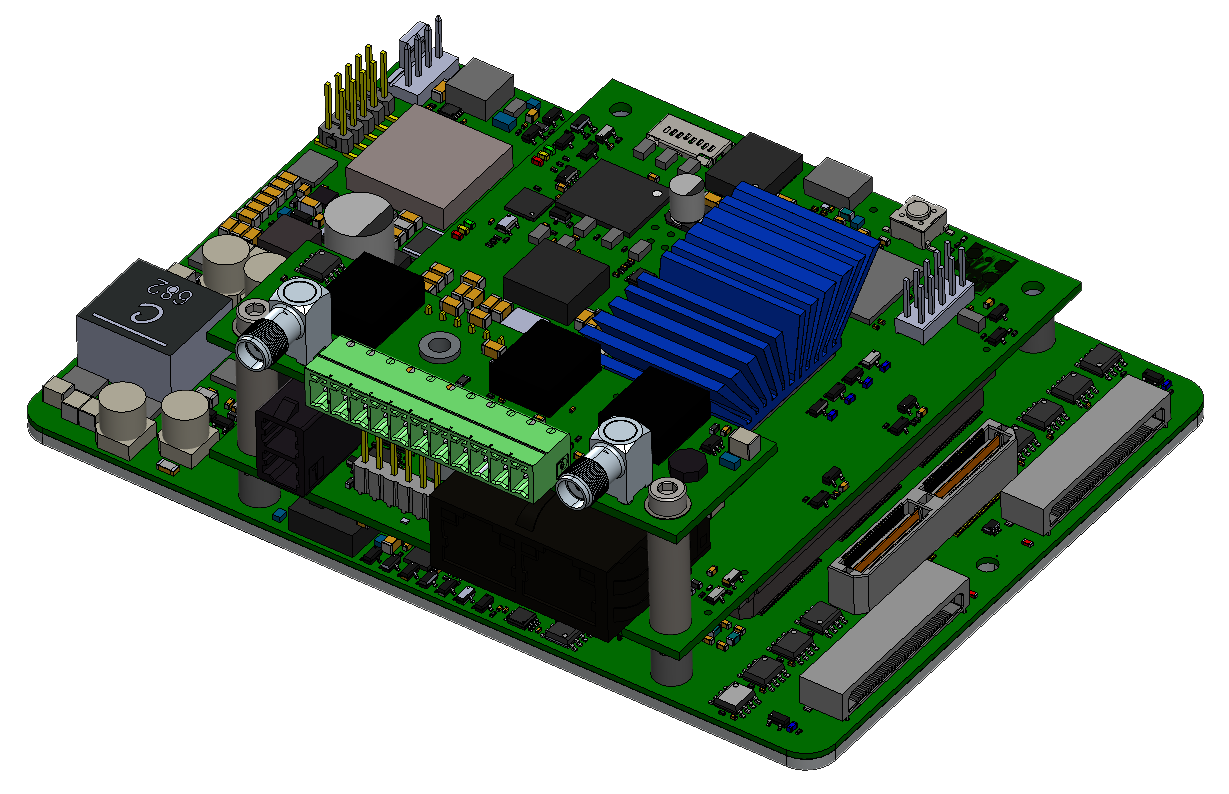
1200607
Signal Manager with Master Relay
- Remove and discard the two M3 bolts that are securing the CPU board to the main board.
- Place and hold a spacer beneath the Signal Manager with Master Relay board and gently fit the board into the desired position, be careful to insert the pins correctly.
- Fit the supplied M3 bolts, washers and nuts.
- Tighten the nut to secure the Signal Manager with Master Relay in place.
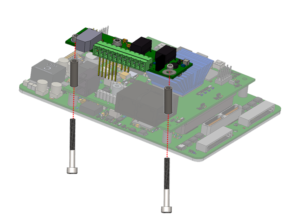
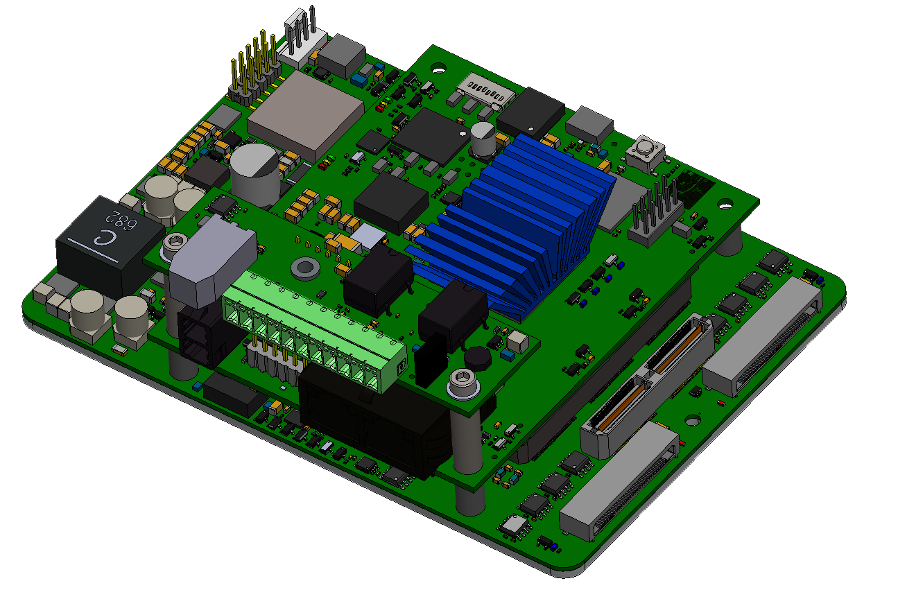
1200491
Printhead Card Expansion Board
- Place the Printhead Card Expansion Board in the desired position, be careful to insert the connector correctly.
- Secure in place with supplied screw (x1).
- Add the second Printhead Card Expansion Board, if required,
- Tighten the nut to secure the Printhead Card Expansion Board in place.